What is G-code
G-code is the generic name for plain-text language that CNC machines can understand. Manufacturers all around the world use CNC programming to control a machine to produce parts, it tells the machine where – and how – to move. Although G-code is supposed to be a universal standard, there are small differences from one machine to another. It really comes down to the capabilities of each machine. For example, the Maslow cnc control board will execute a M106 command as a Laser ON activating a pin on the board to turn the laser ON, while the same M106 command in a Marlin control board will turn the fan at full speed.
When in doubt, always refer to the documentation of your CNC machine.
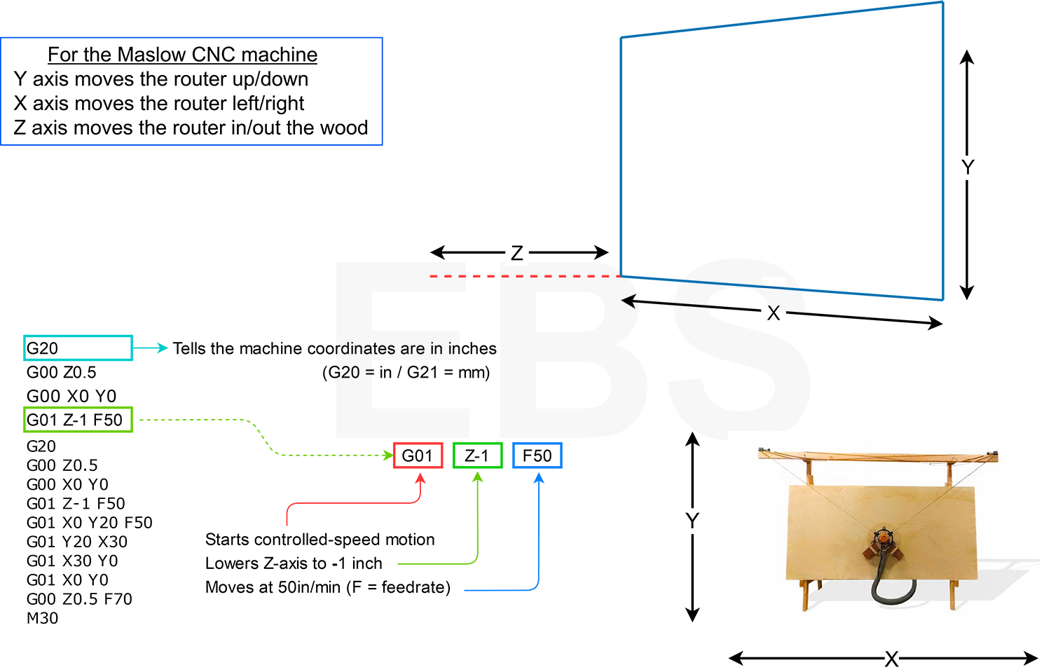
Here is an example of a G-code file that will cut a rectangle.
%
G20
G00 Z0.5
G00 X0 Y0
G01 Z-1 F50
G01 X0 Y20 F50
G01 Y20 X30
G01 X30 Y0
G01 X0 Y0
G00 Z0.5 F70
M30
%
G20
G00 Z0.5
G00 X0 Y0
G01 Z-1 F50
G01 X0 Y20 F50
G01 Y20 X30
G01 X30 Y0
G01 X0 Y0
G00 Z0.5 F70
M30
%
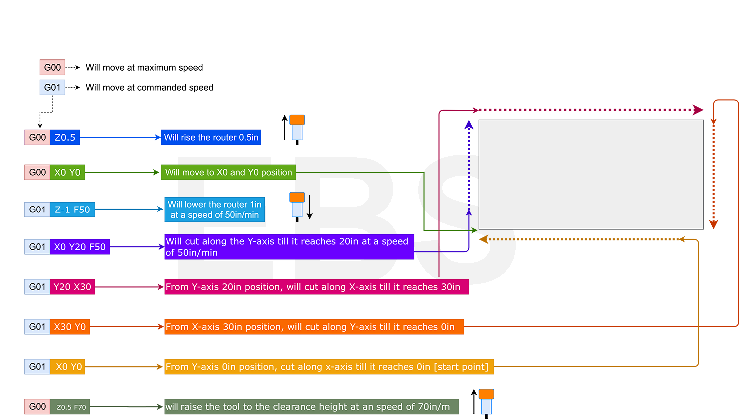
Let's see how it works
Now let's break it down line by line.
List of commands
While the commands are called G code, G is not the only letter used. Different letters dictate how the machine moves and numbers set the parameters.
N The N value gives the line number.
G G commands often tell the control what kind of motion is wanted
X, Y, Z These values indicate the position of the tool in three dimensions — X for horizontal, Y for vertical and Z for depth.
F F relates to how quickly the machine feeds the piece.
S S tells the machine the rpm of the spindle.
T The T tells the machine which tool to use.
M M values give miscellaneous functions or machine functions, telling the device how to act by giving on and off directions.
I, J These values indicate the incremental center of any arcs the machine makes.
R R gives the radius of arcs made by the machine.
A A values direct the tool around the x-axis.
B The number with B shows the rotational value around the y-axis. C An auxiliary axis that rotates around the z-axis gets its positional value from the C value.
D This number shows how much the system offsets the tool diameter.
L L gives the system a value to indicate repeating operations and how many times they need to loop.
P The program jumps in time or a delayed time with the P command.
CODE CATEGORY FUNCTION
G00 Motion Move in a straight line at rapids speed.
G01 Motion Move in a straight line at last speed commanded by a (F)eedrate
G02 Motion Clockwise circular arc at (F)eedrate
G03 Motion Counter-clockwise circular arc at (F)eedrate
G04 Motion Dwell: Stop for a specified time. P for milliseconds X for seconds
G05 Motion Spline Definition
G06 Motion Spline Interpolation
G08 Motion Radius Mode
G09 Motion Exact stop check
G10 Compensation Programmable parameter input
G14 Coordinate Polar coordinate programming, absolute
G15 Coordinate Polar coordinate programming, relative
G16 Coordinate Definition of pole point in polar system
G17 Coordinate Select X-Y plane selection
G18 Coordinate Select X-Z plane selection
G19 Coordinate Select Y-Z plane selection
G20 Coordinate Program coordinates are inches
G21 Coordinate Program coordinates are mm
G27 Motion Reference point return check
G28 Motion Return to home position
G29 Motion Return from the reference position
G30 Motion Return to the 2nd, 3rd, and 4th reference point
G32 Canned Single-point threading, longhand style.
G40 Compensation Tool cutter compensation OFF
G41 Compensation Tool cutter compensation left
G42 Compensation Tool cutter compensation right
G43 Compensation Apply tool length compensation (plus)
G44 Compensation Apply tool length compensation (minus)
G49 Compensation Tool length compensation cancel
G50 Compensation Reset all scale factors to 1.0
G51 Compensation Turn on scale factors
G52 Coordinate Local workshift for all coordinate systems: add XYZ offsets
G53 Coordinate Machine coordinate system (cancel work offsets)
G54 Coordinate Work coordinate system (1st Workpiece)
G55 Coordinate Work coordinate system (2nd Workpiece)
G56 Coordinate Work coordinate system (3rd Workpiece)
G57 Coordinate Work coordinate system (4th Workpiece)
G58 Coordinate Work coordinate system (5th Workpiece)
G59 Coordinate Work coordinate system (6th Workpiece)
G61 Other Exact stop check mode
G62 Other Automatic corner override
G63 Other Tapping mode
G64 Other Best speed path
G65 Other Custom macro simple call
G68 Coordinate Coordinate System Rotation
G69 Coordinate Cancel Coordinate System Rotation
G73 Canned High speed drilling cycle (small retract)
G74 Canned Left hand tapping cycle
G76 Canned Fine boring cyle
G80 Canned Cancel canned cycle
G81 Canned Simple drilling cycle
G82 Canned Drilling cycle with dwell (counterboring)
G83 Canned Peck drilling cycle (full retract)
G84 Canned Tapping cycle
G85 Canned Boring canned cycle, no dwell, feed out
G86 Canned Boring canned cycle, spindle stop, rapid out
G87 Canned Back boring canned cycle
G88 Canned Boring canned cycle, spindle stop, manual out
G89 Canned Boring canned cycle, dwell, feed out
G90 Coordinate Absolute programming of XYZ (type B and C systems)
G90.1 Coordinate Absolute programming IJK (type B and C systems)
G91 Coordinate Incremental programming of XYZ (type B and C systems)
G91.1 Coordinate Incremental programming IJK (type B and C systems)
G92 Coordinate Offset coordinate system and save parameters
G92.1 Coordinate Cancel offset and zero parameters
G92.2 Coordinate Cancel offset and retain parameters
G92.3 Coordinate Offset coordinate system with saved parameters
G94 Motion Units per minute feed mode. Units in inches or mm.
G95 Motion Units per revolution feed mode. Units in inches or mm.
G96 Motion Constant surface speed
G97 Motion Cancel constant surface speed
G98 Canned Return to initial Z plane after canned cycle
G99 Canned Return to initial R plane after canned cycle
======================================================
MASLOW CNC M-codes
======================================================
M0 Program Pause / Unconditional Halt / Stop
M1 Optional Pause / Halt / Sleep
M2 End of Program
M3 Spindle ON
M4 Spindle ON
M5 Spindle OFF
M6 Tool change
M30 Program End with return to program top
M106 Laser ON
M107 Laser OFF
If you have any questions about specific Maslow CNC controller commands, don't hesitate to contact us